The Sequence Diagram is most commonly used by both novice and industry professionals to model the different and unique interactions between objects within a single use case. This includes both the order and the how the parts of the use case interact with each other. The sequence diagram focuses on the part by part execution of a use case.
Sequence Diagrams range from simple to very complex, which is mainly determined by the size and scope of the use case. This tutorial is going to introduce you to various parts of a sequence diagram. To achieve this, we are going to walk through a simple example in order to get your feet wet within the realm of sequence diagrams.
Sequence Diagram Example
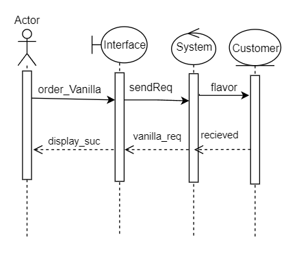
This simple sequence diagram is the represention of a use case where a customer uses an ice cream ordering system to order vanilla ice cream. This is after the size of the ice cream and whether it's in a cup or a cone. The use case goes as follows: As a user I want to select vanilla as flavor of ice cream that I want to order.
The example that we are going to go through is located at the bottom of the page and if you are confused about any of the symbols, the next page explain each one used. To start things off, the first object we are going to cover is the dotted line under each object which is the lifeline, which shows when the object is active through out the sequence of the use case. These can get quite complicated, but we are keeping it simple. The actor simply shows that this sequence diagram starts with a particular use case element. Under the actor, the column present is called an activation bar which is used to indicate that an object has been instantiated to be used in the use case. The solid arrow is called a synchronous message which is exactly how it sounds, each message happens one right after another. Nothing else happens during these messages in the use case. The actor orders vanilla, which is chosen on the interface. The symbol that the interface is represented by is a boundary, which is simply a system boundary. The interface then contacts the system through another synchronous message. The system is represented by a control element, which serves as a manager between boundaries and entities. The system then sends the customer entity the flavor that has been chosen. The customer object is represented by an entity, which holds all of the data present with the current customer.
Now starts the return messages. The return message is the dotted arrow that goes back to each of the activation bars. This tells the object that the object has finished the request. In this example, the customer entity tells the system that it has processed and saved the request, then the system tells the interface that the request has been fulfilled. The actor than recieves a notification confirmation that the flavor that they have selected has been recieved. This concludes this sequence diagram, please continue onto the next page to review and learn some other symbols the sequence diagram uses.
