CIS 375 SOFTWARE ENGINEERING
UNIVERSITY OF MICHIGAN-DEARBORN
DR. BRUCE MAXIM, INSTRUCTOR
Date: 10/13/97
Week 6
- Structured analysis and design technique(SADT)
Structured analysis activity diagram:
(Activity Network)
Control
Inputs Output
Mechanism
Structured analysis data diagram:
(Data Network)
Control
Generating Activity Resulting Activity
Storage Devices
Design techniques:
Explains how to interpret results of SA (control issues).
- Structured system analysis:
- Use data flow diagram.
- Use data dictionaries.
- Use pseudocode algorithms (control inf.)
- Use relational data tables to indicate data elements
and relations.
- Requirements dictionary:
- All system elements.
- Dictionary format:
- 1) Name.
- 2) Aliases.
- 3) Where something's used & how it is used
(producer & consumer).
- 4) Content description (motivation for representation).
- 5) Supplementary information - restrictions,
limitations.
OBJECT ORIENTED ANALYSIS
OBJECT ORIENTED DESIGN
IDENTIFY THE PROBLEM OBJECTS
(classes) = nouns (not procedure names)
Example:
- 1) External entities (people & devices).
- 2) Things in problem domain (reports, displays,
signals).
- 3) Occurrences or events (completion of some
task).
- 4) Roles (manager, engineer, sales person).
- 5) Organizational units (division, groups, department).
- 6) Structures (sensors, vehicles, computers).
CRITERIA:
(Object or not)
- 1) Does object inf. need to be retained?
- 2) Does object have a set of needed services?
- (Can change it's attributes)
- 3) Does the object have major attributes?
- (Trivial objects should not be built)
- 4) Identify common attributes for all object
instances.
- 5) Identify common operations for all object
instances.
- (If nothing to share, why make it an object?)
- External entities which produce or consume must
have defined classes.
SPECIFYING ATTRIBUTES:
Similar to building data dictionary.
(define in terms of atomic objects)
SPECIFYING OPERATIONS:
- Include anything needed to manipulate data elements.
- Communication among objects.
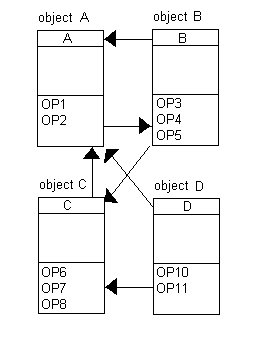
OBJECT SPECIFICATION:
- Object name.
- Attribute description:
- Attribute name.
- Attribute content.
- Attribute data type/structure.
- External input to object.
- External output from object.
- Operation description:
- Operation name.
- Operation interface description.
- Operation processing description.
- Performance issues.
- Restriction and limitations.
- Instance connections:
(0:1, 1:1, 0:many, 1:many)
- 6.1. Message connections.
OBJECT ORIENTED ANALYSIS STEPS:
- Class modeling.
- (Build an object model similar to an ER diagram)
- Dynamic modeling.
- (Build a finite state machine type model)
- Functional modeling.
(Similar to data flow diagram)
CASE STUDY:
ELEVATOR MODEL.
n - elevators.
m - floors in building.
each floor has two buttons (except ground & top).
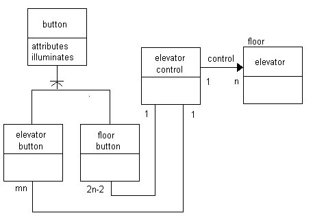
CLASS MODELING
- Buttons.
- Elevators.
- Floor.
- Building.
- Movement.
- Illumination.
- Doors.
- Requests.
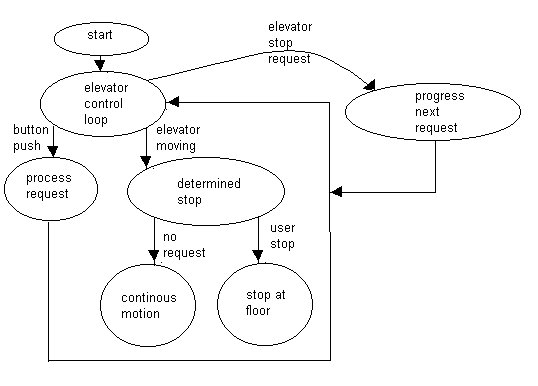
DYNAMIC MODELING:
"Normal" schemas (and 1 or 2 abnormal).
-> production rules (describe state transitions).
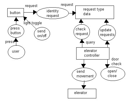
FUNCTIONAL MODELING:
(Identify source & destination node)
OBJECT-ORIENTED LIFE CYCLE MODEL:
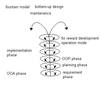
FOUNTAIN MODEL:
Bottom up design.
Date: 10/15/97
Week 6
CLASS RESPONSIBILITY COLLABORATOR MODEL (CRC):
Responsibilities:
- Distributed system intelligence.
- State responsibility in general terms.
- Information and related behavior in same class.
- Information attributes should be localized.
- Share responsibilities among classes when appropriate.
- Collaborators build a CRC card
(Build a paper model, see if it works on paper)
On card:
- Class name.
- Class type.
- Class characteristics.
- Responsibility/collaborators.
(System is basically acted out)
MANAGEMENT & OBJECT ORIENTED PROJECTS:
- Establish a common process framework (CPF).
- Use CPF & historic data to eliminate time & effort.
- Specify products & milestone.
- Define Q.A. checkpoints.
- Manage changes.
- Monitor.
Project Metrics:
- 1) Number of scenario scripts.
- 2) Number of key classes.
- 3) Number of support classes.
- 4) (# of key classes)/(# of support classes).
OBJECT ORIENTED ESTIMATING & SCHEDULING:
- Develop estimates using effort decomposition, FP, etc.
- Use O.O.A. to develop scenario script and count them.
- Use O.O.A. to get the number of key classes.
- Categorize types of interfaces:
- No U.I. = 2.0 G.U.I. = 3.0
- Text U.I. = 2.25 Complex G.U.I. = 3.0
- Use to derive support classes:
- (# of key classes) * (G.U.I. #)
- Total classes = (key + support) * (average # of work units
per class).
- ( 15-20 person days per class)
- Cross check class based estimate (5) by multiplying.
- (avg. # of work units) * (# of scenario scripts)
PROJECT SCHEDULING METRICS:
- Number of major iterations (around spiral model).
- Number if completed contracts.
(Goal: at least 1 per iteration)
OBJECT ORIENTED MILESTONES:
- Contracts completed.
- O.O.A. completed.
- O.O.D. completed.
- O.O.P. completed.
- O.O. testing completed.
SYSTEM DESIGN:
- Conceptual Design (function) {for the customer}.
- Technical design (form) {for the hw & sw
experts}.
CHARACTERISTICS OF CONCEPTUAL DESIGN:
- Written in customer's language.
- No techie jargon.
- Describes system function.
- Should be implement independent.
- Must be derived from requirements document.
- Must be cross referenced to requirements document.
- Must incorporate all the requirements in adequate detail.
TECHNICAL DESIGN CONTENTS:
- System architecture (sw & hw)
- System software structure.
- data
DESIGN APPROACHES:
- Decomposition (function based, well defined).
OR
- Composition (O.O.D., working from data types not values).
PROGRAM DESIGN:
- Defining modules and their interfaces.
- Each system module is rewritten as a set of program specifications
(input, output, process).
PROGRAM DESIGN MODULES:
- Must contain detailed algorithms.
- Data relationships & structures.
- Relationships among functions.
PROGRAM DESIGN GUIDELINES:
- Top - down approach.
- vs.
- Bottom - up approach.
- (There are risks and benefits for both)
- Modularity & independence (abstraction).
- Algorithms:
- Correctness.
- Efficiency.
- Implementation.
- Data types:
- Abstraction.
- Encapsulation.
- Reusability.
WHAT IS A MODULE?
A set of contiguous program statements with:
- 1) A name.
- 2) The ability to be called.
- 3) Some type of local environment (variables).
- (Self contained, sometimes can be compiled separately)
- Modules either contain executable code or creates data.
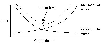
DETERMINING PROGRAM COMPLEXITY:
{More modules - less errors in each, but more errors between
them}
PROGRAM COMPLEXITY FACTORS:
- 1. Span of the data item.
- (too many lines of code between uses of a variable)
- 2. Span of control.
- (too many lines of code in one module)
- 3. Number of decision statements.
- (too many "if - then - else", etc.)
- 4. Amount of information which must be understood.
- (too much information to have to know)
- 5. Accessibility of information and standard presentation.
- (x,y -> x,y; not y1,y2)
- Structured information.
- (good presentation)


