CIS 375 SOFTWARE ENGINEERING
UNIVERSITY OF MICHIGAN-DEARBORN
DR. BRUCE MAXIM, INSTRUCTOR
Date: 10/6/97
Week 5
SYSTEM ANALYSIS OBJECTIVES:
- Identify customer's needs.
- Evaluate system for feasibility.
- Perform economic and technical analysis.
- Allocate functions to system elements.
- Establish schedule and constraints.
- Create system definitions.
MANAGEMENT QUESTIONS:
- How much effort put towards analysis?
- Who does the analysis?
- Why is it so difficult? (Bottom line - who pays
for it?)
FEASIBILITY STUDY:
- Economic feasibility. (cost/benefit analysis)
- Technical feasibility. (hw/sw/people, etc.)
- Legal feasibility.
- Alternatives.
MODELING SYSTEM ARCHITECTURE:
- Architecture template.
| User Interface Processing
|
Input Processes |
Process & Control Functions
|
Output Processes |
| Maintenance &
Self-Test
| |
- Architecture context diagram.
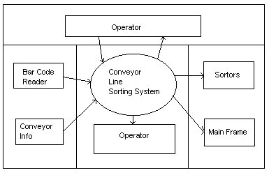
- Architecture flow diagram:
- Much greater detail.
- specific inputs/outputs/parameters are needed.
- Architecture diagram specification:
- System module narrative for each subsystem (purpose,
processing interface).
- Architectural dictionary.
- Architectural interconnect diagram (directed
graph, the nodes are AFD's).
SYSTEM SPECIFICATIONS:
- Introduction.
- Functional data description.
- Subsystem description.
- System modeling and simulation results.
- Projects.
- Appendices.
REQUIREMENTS ANALYSIS:
- Requirement- features of system or system function
used to fulfill system purpose.
- Focus on customer's needs and problem; not solutions:
- Requirements definition document (written for customer).
- Requirements specification document (written for programmer;
technical).
TYPES OF REQUIREMENTS:
- Functional requirements:
- Input/output processing.
- Error handling.
- Non-functional requirements:
- Physical environment (equipment locations, multiple sites,
etc.).
- Interfaces (data medium etc.).
- User & human factors (who are the users, their skill level
etc.).
- Functionality (how well is system functioning).
- Documentation.
- Data (qualitative stuff).
- Resources (finding, physical space).
- Security (backup, firewall).
- Quality assurance (max. down time, MTBF, etc.).
VALIDATION OF REQUIREMENTS (HOW TO CHECK TO
SEE WHAT'S THERE):
- Correct?
- Consistent?
- Complete?
- Externally - all desired properties are present.
- Internally - no undefined references.
- Each requirement describes something actually needed by the
customer.
- Requirements are verifiable (testable)?
- Requirements are traceable.
REQUIREMENTS DEFINITION DOCUMENT:
- General purpose of document.
- System background and objectives.
- Description of approach.
- Detailed characteristics of proposed system (data
& functionality).
- Description of operating environment.
F.A.S.T. - FACILITATED APPLICATION SPECIFICATION
TECHNIQUE (YOU & CUSTOMER GET TOGETHER EARLY TO
GET EVERYTHING "HAMMERED" OUT. FOCUS ON PROBLEM DEFINITION):
- Meeting between customers and developers at a neutral site
(no home advantage).
- Rules for participation and preparation established ahead
of time.
- Agenda suggested (brain storming).
- Facilitator appointed.
- Definition mechanism (sheets, flipcharts, wallboards, stickers,
etc.).
- Goal - identify the problem, propose elements of solution,
negotiate different approaches, specify preliminary set of requirements.
QFP - QUALITY FUNCTION DEPLOYMENT (CUSTOMER'S
NEEDS -> TECHNICAL REQUIREMENTS):
- Normal requirements (minimal functional & performance).
- Expected requirements (important implicit requirements, i.e.
ease of use).
- Exciting requirements (will become normal req. next time,
highly prized & valued).
FUNCTION DEPLOYMENT:
INFORMATION DEPLOYMENT:
TASK DEPLOYMENT:
VALUE ANALYSIS:
MAKES USE OF:
- Customer interviews.
- Observations.
- Surveys.
- Historical data.
ANALYSIS PRINCIPLES:
- Information domain of problem must be presented
& understood.
- Models depicting system information, functions, and behavior
should be developed.
- Models and problems must be partitioned in a manner that uncovers
detail in layers.
- Analysis proceeds from essential information toward implementation
detail (must be traceable).
SPECIFICATION PRINCIPLES:
- Separate functionality from implementation.
- A processor - oriented specification language
is needed.
- Specification must encompass the system containing the software
component.
- Specification must encompass the environment.
- System specification = cognitive model.
- Specification must be operational (talk about how it works).
- Must be tolerant of incompleteness and easy to add to.
- Specification must be localized and loosely coupled (pieces
of things are independent of each other).
Date: 10/8/97
Week 5
REQUIREMENTS REVIEW:
- Goals & objectives review.
- Compare requirements to goals & objectives.
- Consider system operating environment.
- Assess and document all risks in system developmental
operation.
- Discuss testing procedure.
EVALUATING SPECIFICATION TECHNIQUES:
- Requirements are understandable to naïve user.
- Requirements form basis for design and testing.
- Automated requirements checking?
- Requirements form external view of system.
- Technique aid in organizing and structuring requirements.
- Technique for prototyping.
- Automatic test case generation from requirements.
- Appropriate for application.
ERPP:
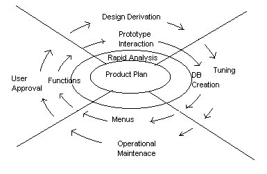
RISKS USING ERPP:
- Premature delivery.
- Premature design selection.
- Features in prototype can get lost in final product.
- There is a tendency to choose efficiency over modifiability
- Focus on what will take least amount of program time rather
than maintainability.
- Rapid prototyping - don't write code until ready, with spiral
model may want to write code, but code may be thrown out after
risk assessment.
REQUIREMENTS ANALYSIS FOR ERPP:
What.
When.
Cost.
Completion.
Re-use.
Contingencies.
Rewards.
DESIGN:
(Always has one process, even in ERRP model)
Conversion at requirements into algorithms and data structures.
Need to work on "this part of system" , need to
get this working.
IMPLEMENTATION & TESTING:
- Code.
- Test.
- Debug.
- Goto 1 (repeat).
FINAL SPIN CYCLE:
Each module is evaluated:
- Leave as is.
- Rewritten.
- Replace with existing code.
- Discard, as no longer needed.
Reimplementation symptoms:
1) Prototype -> spaghetti code.
- Prototype -> cannot be extended to meet full user requirements.
- Work to fix -> work to start again.
REQUIREMENTS SPECIFICATION METHODS:
- HIPO Chart:
(Hierarchy Input - Output Chart)
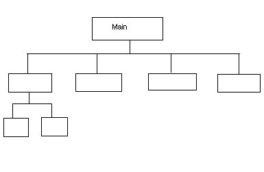
Strengths Weaknesses
- Shows function - No mechanism for
relationship. Non-functional requirements.
- No checking mechanism.
- Hierarchical Data Structures:
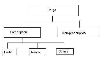
How is it different from object hierarchy:
- Looks at data, not methods.
- No inputs/outputs.
- Only shows declaration of records, could work for database
model, but not for implementation.
- Data Flow Diagrams:
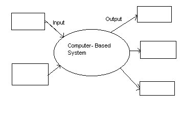
{square} = producer or consumer of information.
{circle} = software client capable of transforming information.
{arrow} = data item.
{thing} = database.
Key: this is data flow.
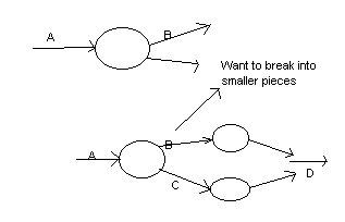 PSPEC - process specification.
- CFD:
Control flow diagram.
CSPEC - control specification.
- General Data Model: (Focus on data)
Data object tables are determined.
Object = record.
Attribute = fields.
NORMALIZATION RULES:
- Given instance of an object has one value for an attribute.
- Attributes represent elementary items.
- When more than one attribute is used to identify an object,
make sure they describe the same "key".
- All non-ID attributes represent the same characteristics of
instance named by key.
E-R DIAGRAM:
(Entity relationship)
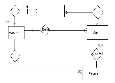 {squares} = data object.
{diamonds} = relationship between objects.
- Decision Table:
| Rules
| |
| Condition | 1
| 2 | |
| Rules
| |
| Actions | 1
| 2 | |
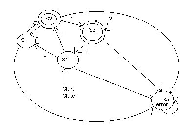
- Finite state machines:
- Set of machine states.
- So , start state.
- F , final state.
- Input symbols - .
- Transition functions - : * .
- Event table:
(Like decision table)
- Vertical axis that deals with system nodes or states.
- Horizontal axis - events (clicks on mouse).
- Table entries - action (displaying menu).
| Mode | Event1
| Event2 | Event3
| Event4 |
| Presentation Graphics |
Action1 |
Action8
|
O |
X
|
| Architecture
Drawing
|
X |
A2 then A3
|
A5 & A6 |
O
|
| Programming | O
| A4 | A1, A2 & A3
| A7 |
O = no action / no state change.
X = no action defined.
- Petri Net:
- Sequential processes.
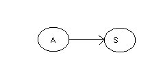
f(state A, event) -> state S.
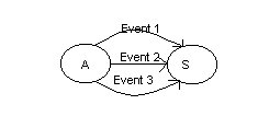
f(state A, event1, event2, event3) -> state S.
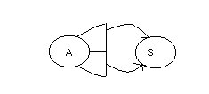
f(state A, event1, event2, event3) -> (state S1,
state S2).


